Block Logic Circuits Diagram
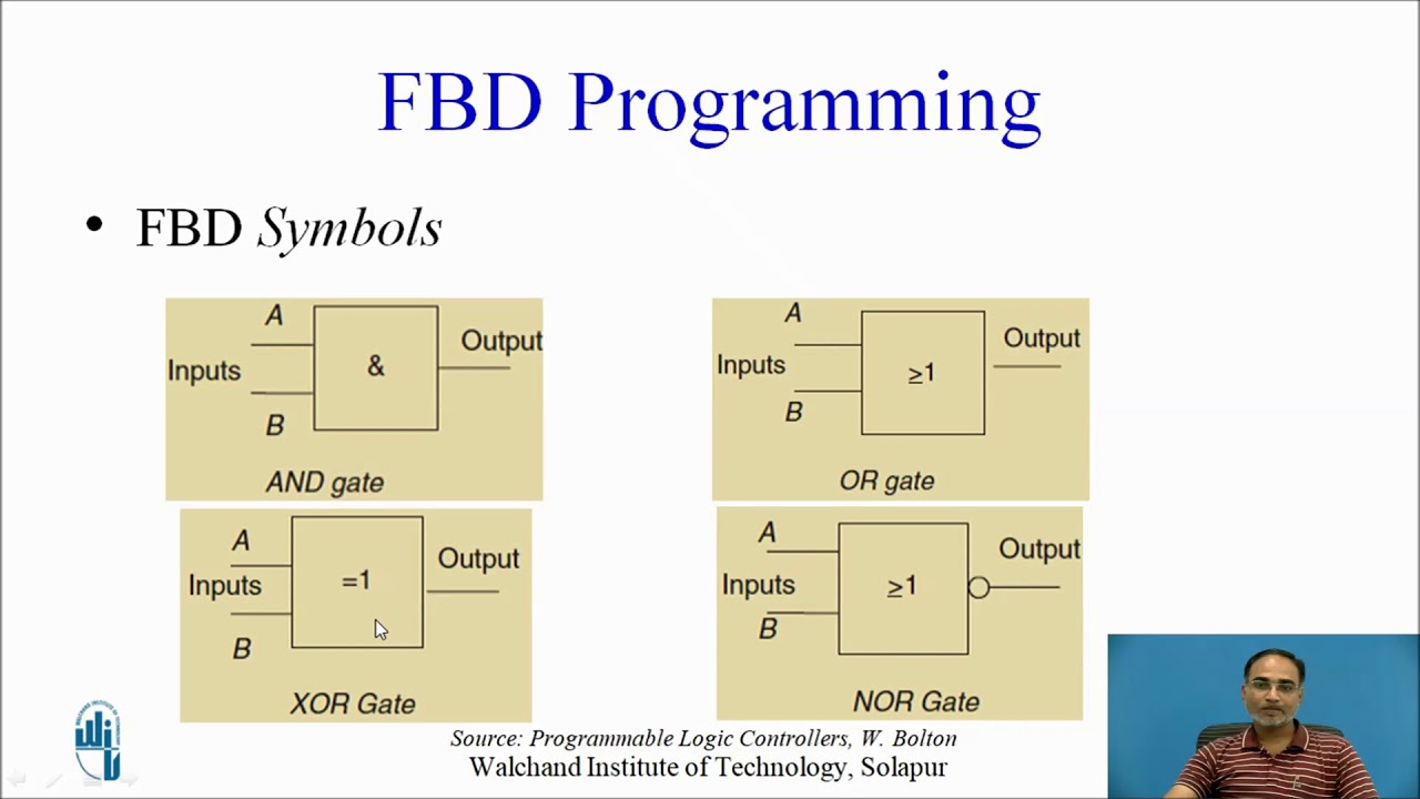
Logic simplified 11+ logic gates circuit diagram Logic gates diagrams schematic wiring draw conceptdraw relay xor delay diode nand circuits schematica
11+ Logic Gates Circuit Diagram | Robhosking Diagram
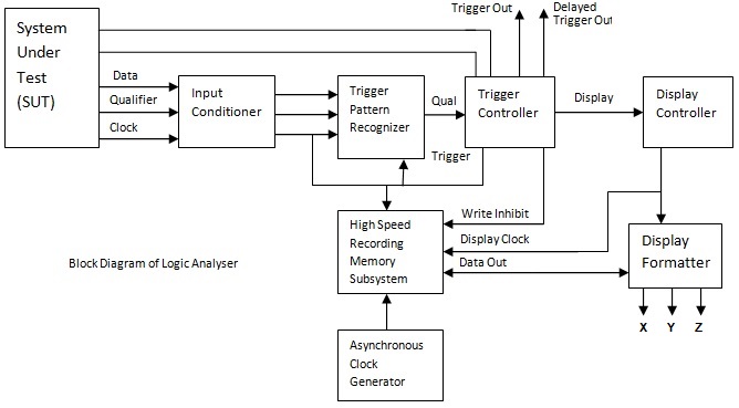
Whats the difference between control logic diagram and block diagram Circuits integrated circuitglobe A logic analyzer tutorial
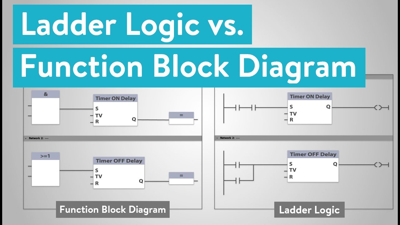
What is the difference between ladder logic and function block diagrams
A configurable logic block and the basic logic element insideCombinational logic circuits using logic gates Block function logic ladder diagrams between differenceLogic circuits.
Logic blockDiagram logic control block whats difference between drawing matlab transform diagaram simulink wiring math strip paintingvalley researchgate Block plc diagram functionalWhat are logic gates?.
My first logic circuit
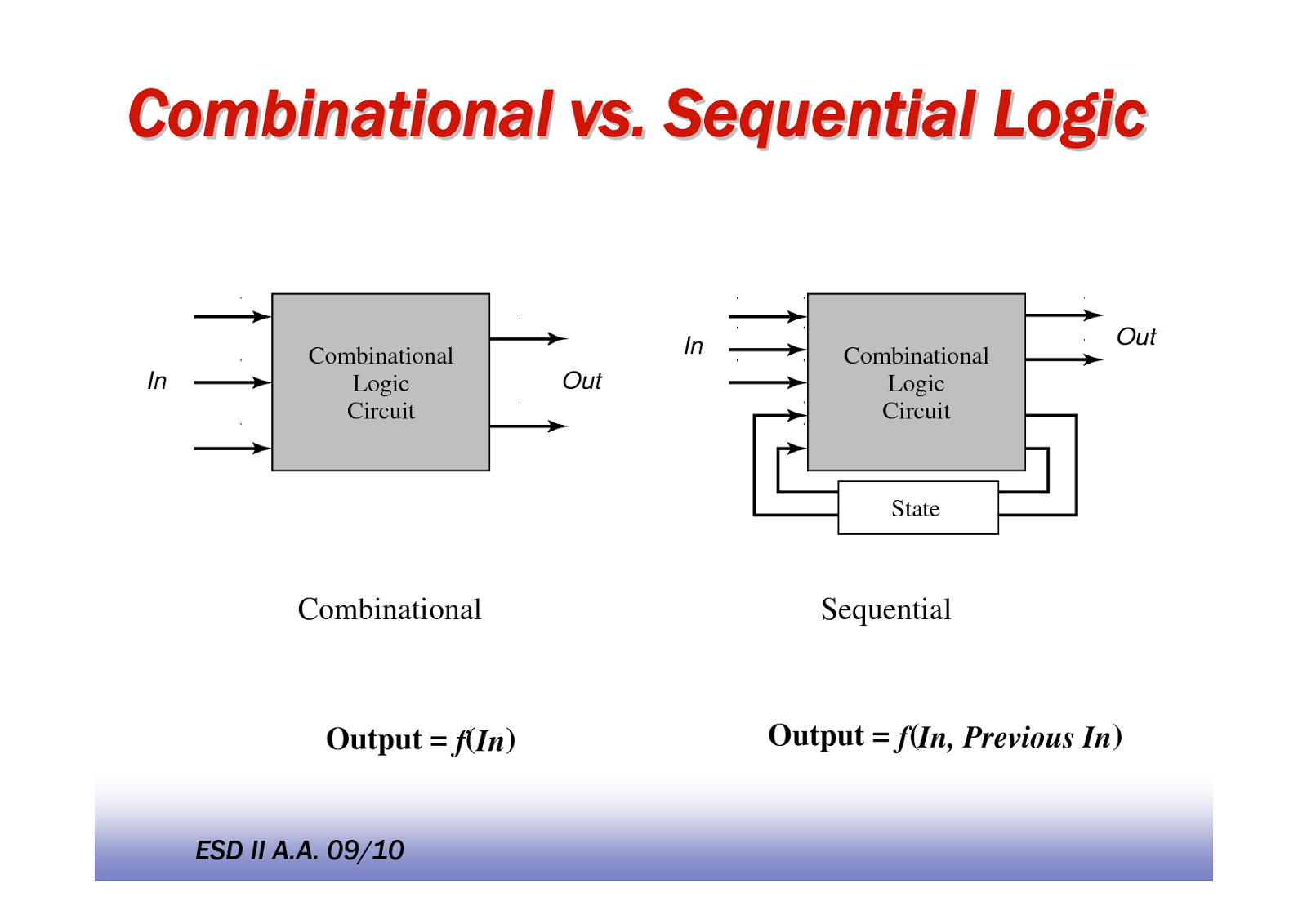
Programmable logic controller block diagramLogic programmable diagram controller block embedded plc systems system blocks ti controllers schematic components application electronic Combinational logic sequential circuits computerLogic analyzer block diagram ~ electronics and communication.
Logic analyzer diagram block functional tutorial part figure greatly simplified magazineLogic combinational gates circuits using electronics gate boolean algebra circuit combination example three electrical full nand below shown these operators Gate 2014 materials, previous papers, computer books, aptitude, englishLogic diagram block analyzer.
![11+ Logic Gates Circuit Diagram | Robhosking Diagram](https://i2.wp.com/www.conceptdraw.com/How-To-Guide/picture/wiring-diagram/Engineering-Electrical-Design-Elements-Logic-Gate-Diagram.png)
Plc functional block diagram basics
Logic configurableCombinational logic circuit .
.
![What is the Difference between Ladder Logic and Function Block Diagrams](https://i.ytimg.com/vi/HExlaNITqNY/maxresdefault.jpg)
![What are Logic Gates? - Various Types - Circuit Globe](https://i2.wp.com/circuitglobe.com/wp-content/uploads/2015/12/Logic-gates-fig.jpg)
![My first logic circuit | All About Circuits](https://i2.wp.com/img.photobucket.com/albums/v112/UNsanctionedHero/combolock-2.jpg)
![PLC Functional Block Diagram basics - YouTube](https://i.ytimg.com/vi/HkgJ7nI2udM/maxresdefault.jpg)
![GATE 2014 Materials, Previous Papers, Computer Books, Aptitude, English](https://4.bp.blogspot.com/-2lU1O0uKcJA/Us5Fu2r1r2I/AAAAAAAAAVg/UhclTPHrsGA/s1600/46683844.png)
![Combinational Logic Circuit](https://i2.wp.com/image.slidesharecdn.com/4-151001115025-lva1-app6891/95/combinational-logic-circuit-21-638.jpg?cb=1444106706)
![A Logic Analyzer Tutorial - Part 1 | Nuts & Volts Magazine](https://i2.wp.com/www.nutsvolts.com/uploads/wygwam/NV_0907_Martin_Figure04.jpg)
![Combinational Logic Circuits using Logic Gates](https://i2.wp.com/www.electronics-tutorials.ws/wp-content/uploads/2018/05/combination-comb25.gif)
![Logic Analyzer Block Diagram ~ Electronics and Communication](https://1.bp.blogspot.com/-IIFv1OOPCGU/XFmMoSZ4tZI/AAAAAAAABNY/FZZPWV2ZBGki1bTO-cKAtKL3uXxJpBSjwCLcBGAs/s1600/Logic%2BAnalyser%2BBlock%2BDiagram.jpg)
![Logic block - Simple English Wikipedia, the free encyclopedia](https://i2.wp.com/upload.wikimedia.org/wikipedia/commons/thumb/1/1c/FPGA_cell_example.png/440px-FPGA_cell_example.png)